
mke
HalfDork
12/5/19 12:29 p.m.
oldeskewltoy said:
So... if you missed what was wrong with the gasket.... I made a quick and simple gif....
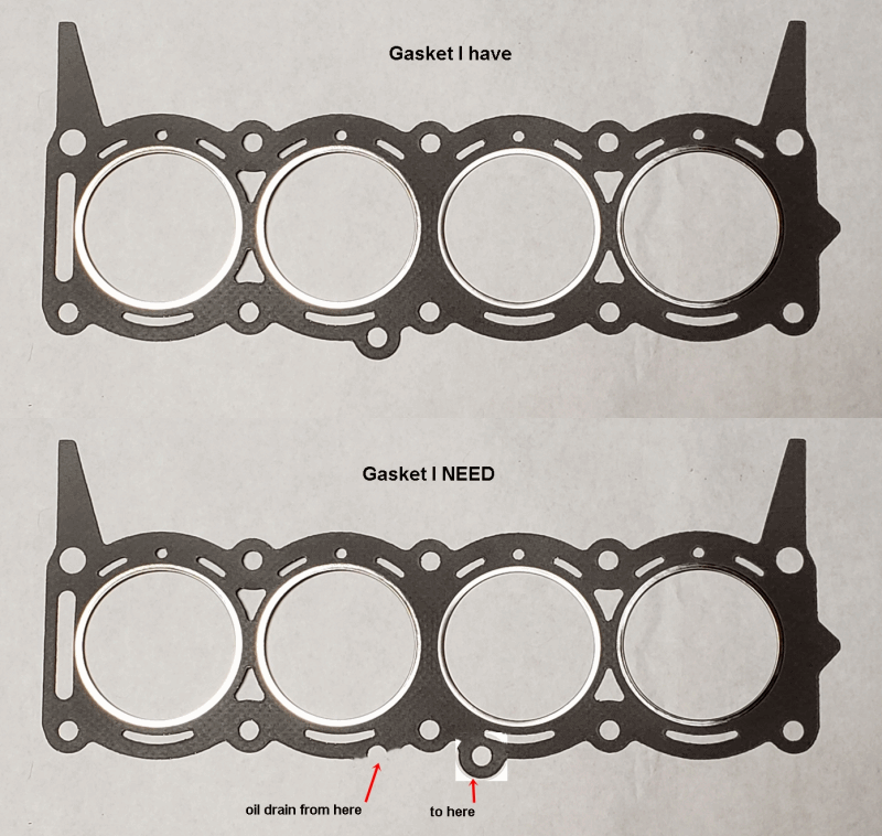
more to come..... 
If that is just an oil drain you could just clip it off and either stick it on with a little sealant when you're placing the gasket or just use a little silicone....I've used silicone for oil drains and water in the past with no issue.
Well... Cometic is trying to correct this...
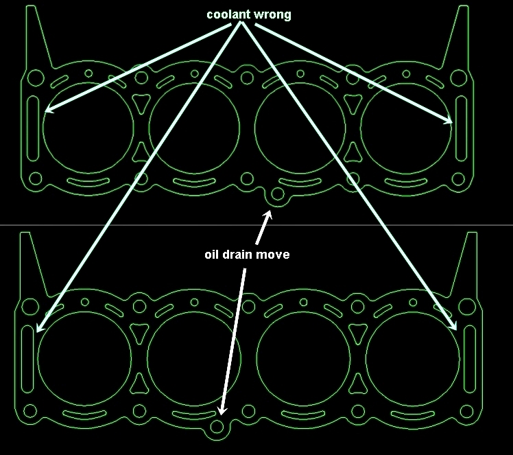
but decided that instead of speculating, they asked me to send back in the used gasket. This time, I'm just sending the old gasket that they didn't make so there wont be any confusion.
More to come...... 
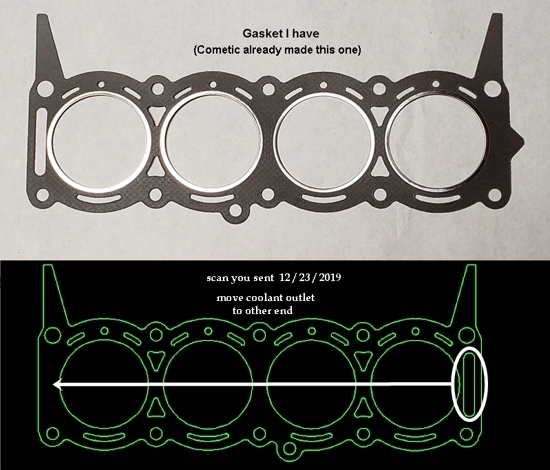
oldeskewltoy said:
This time, I'm just sending the old gasket that they didn't make so there wont be any confusion.
Not sure what the issue is.....
They sent me this....(green).... while now having one end closed, it is the gasket I already have - Cometic already made.....
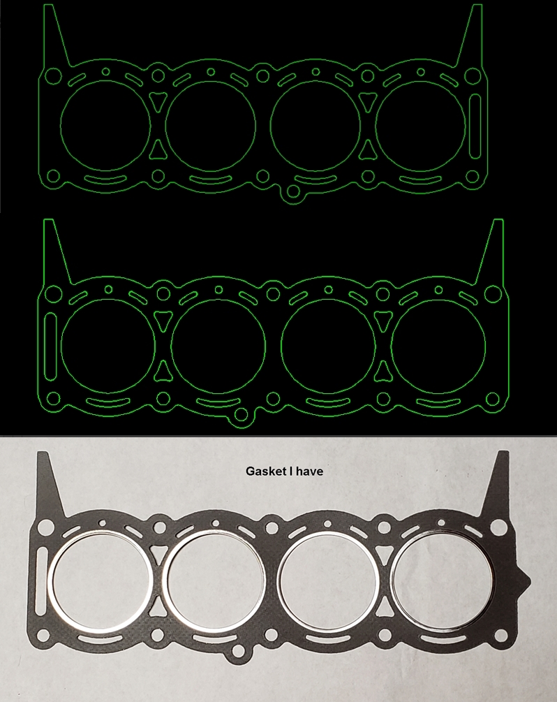
What I NEED is the opposite one..... so I sent this back to Cometic....... HOPEFULLY after the holiday they can get this right.... 
So... while I wait to see if Cometic got it right this time....
Let's see if we have any really smart people in here.... can anyone tell me what we are doing... and why it is important...... 
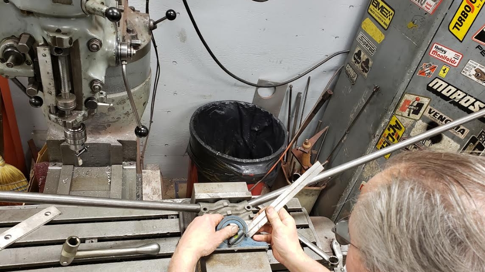
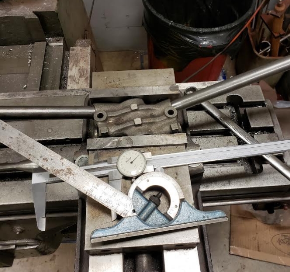
anyone...???
oldeskewltoy said:
anyone...???
Milling a bit off the camshaft cap before line boring it?
Milling camshaft saddles to keep the pushrod geometry with milled cylinder heads.

"from another forum"
Protractor to set properly the angle on the new push rod "guide" ?
(Push rod stuff are totally uncommon here so I have no idea)
On a side note, clamping that cast piece directly on the vice make me cringe. I hope they are soft jaw.
I would have gone with a 1 2 3 block and strap clamps, or better, an aluminium block with tapped hole matching the one on the part (even for a "one time" job it would make sense since you have 4 of them)
The vice is only holding the lifter bore housing so we could insert the bar stock into the lifter bores so we could measure "lifter bank angle".
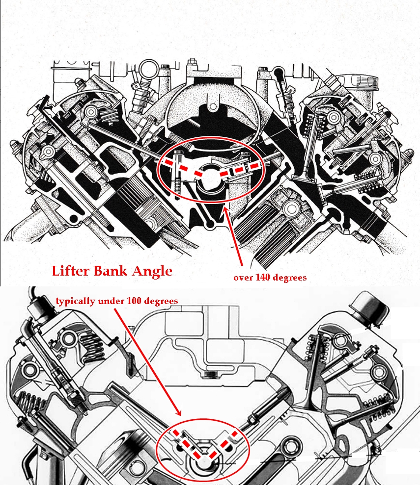
Without knowing the lifter bank angle we can not hope to learn the camshaft lobe center lines.
Why do we need to know that?? I'm changing the whole engine, all the specs I found show peak power occurring @ about 4400 rpm, additionally it originally was designed for use in their top of the line limo - so smooth operation/idle was important. I'm changing all of that, I'm hoping to push peak power rpm to about 5600(redline @ 6000), and to introduce a small amount of lope at idle ;)
Sooo... the camshaft centerline is now the focus, for a smooth idle, and low rpm peak power, the likely centerline is around 116 to 118, maybe even higher, but to attain my goal, the likely centerline is closer to 110-112, maybe even less.....
more to come.... 
By jove, I think they got it.........
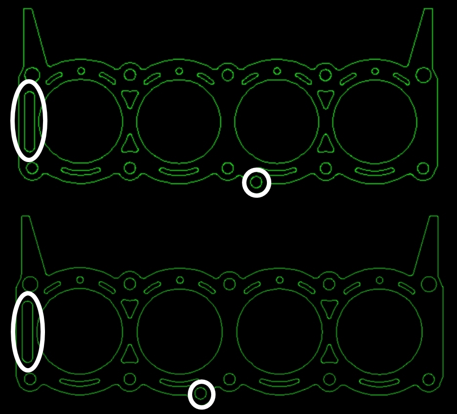
I'll be more careful this time when they arrive, I'll lay them on the heads and check ALL the details...
more to come..... 
How's your Russian?? My 5V is on youtube... well some of it anyway... 
oldeskewltoy said:
Well, the new valve tool is ready..... I'm only using test springs in there, so it doesn't have to be too stout.
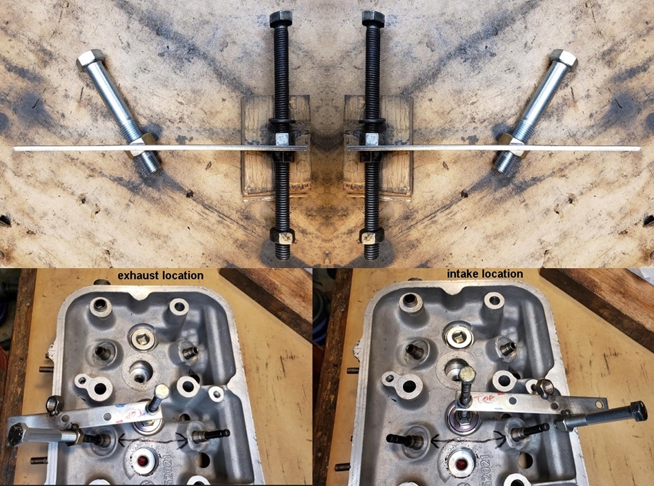
now I just need the time to finish the set up, and calibrate the bench(new set up)
more to come.... 
Yeah..... no.
This set up was a poor design... I couldn't get steady reliable settings - the arm was just too far, so I've been waiting on a better design....
and a better one arrived......
..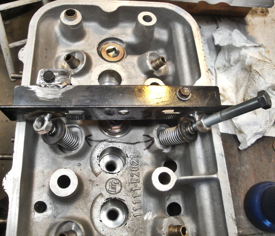
should be very steady/reliable..........
drum roll, please........
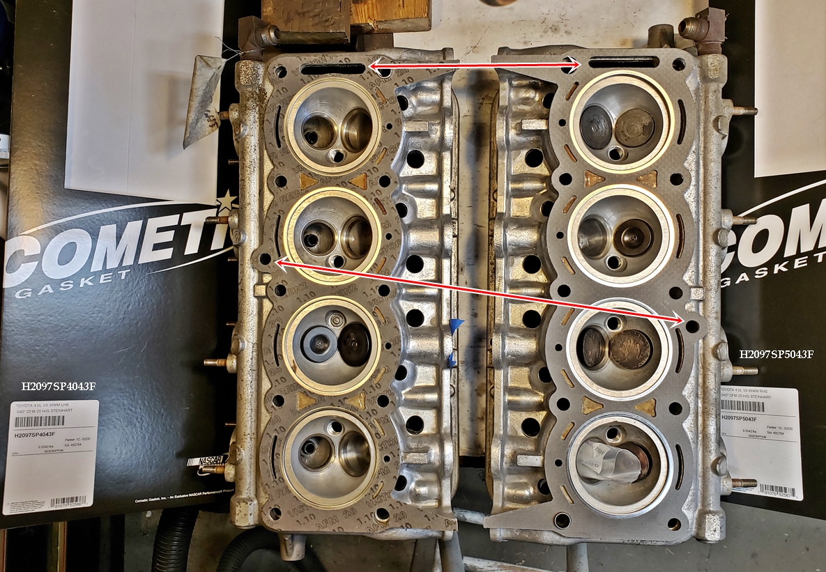
more to come.... 
So, the first two head gaskets you got are correct?
wheelsmithy said:
So, the first two head gaskets you got are correct?
the first two... were both one(the same) side... I now have one for each side
I spent a while looking, but never found anyone who had flowed a Toyota 5V hemi head before... so I did.
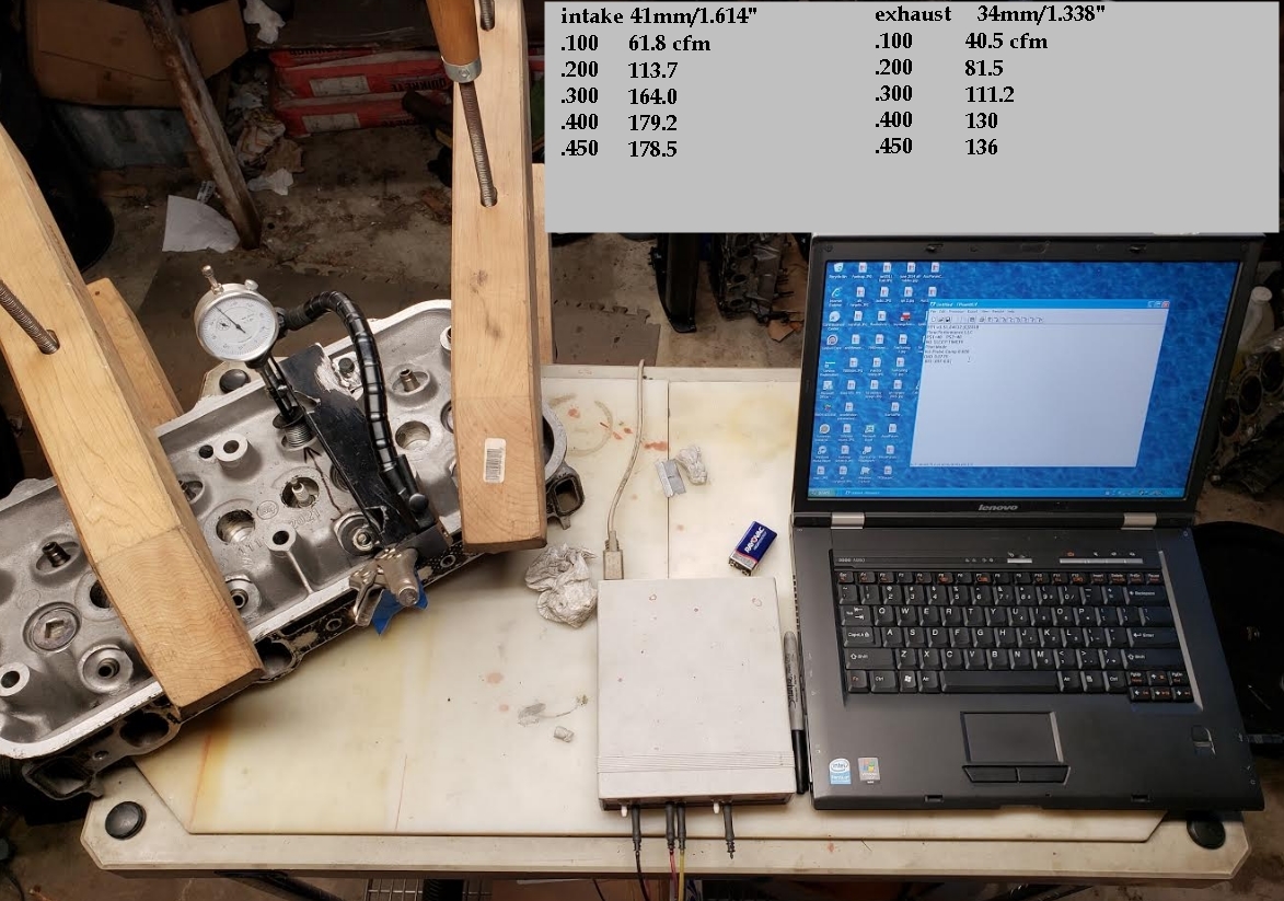
That is pretty good, especially considering valve size.
As to bench racing numbers, that port should support up to about 340-360 n/a hp
more to come.... 
Very cool.
Can you show more of your set up?
TVR Scott said:
Very cool.
Can you show more of your set up?
What would you like to see???

fwingo
New Reader
2/21/20 3:55 p.m.
oldeskewltoy said:
How's your Russian?? My 5V is on youtube... well some of it anyway... 
If you turn on auto-generated closed captions then set auto-translation to English it does a good job of translating the voice over.

bgkast
PowerDork
2/21/20 4:19 p.m.
In reply to oldeskewltoy :
I didn't realize it was your engine in the video until I saw the logo on the shirt of the guy holding the heads!

centerlines are now known... and my guess was wrong........ I had thought they were 116+ do to the smooth idle, and the short powerband... I was wrong! The cam has a 110 degree centerline.... no need to screw with moving it! So, the word is out to the cam grinder that we want to twist this baby to 6000, and to get as much lift as we can - do to base circle, valve lift will be max of about .450"
As to the timing cover and water pump - the plan is no gasket, just anaerobic sealant.
The plan has changed.... I'm sending the timing cover into Cometic they can scan both sides... I'll feel more confident with gaskets....
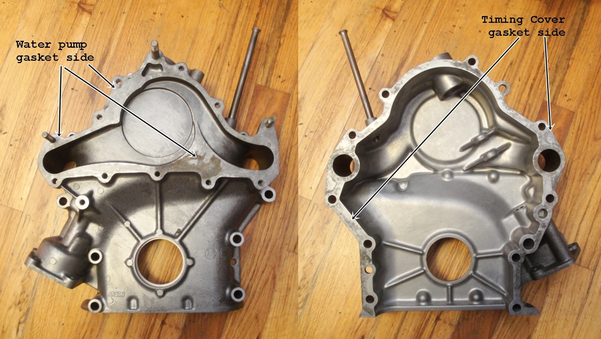
more to come.... 
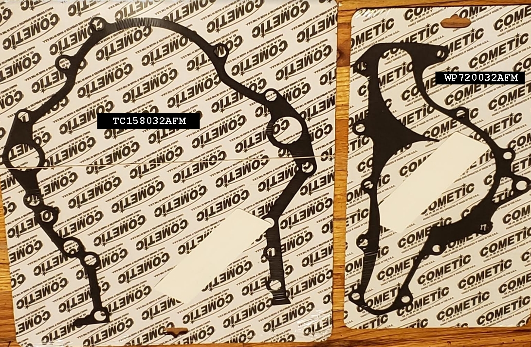
So... with the timing cover and water pump gaskets now in hand... that means we have nearly all the gaskets we'll need (both head gaskets, all exhaust gaskets, both intake gaskets, and now timing cover and water pump. Still working on valve seals.........
.... and pistons.... While there are still one or two unknowns (possible pin offset?) the dome volume has been settled @ 21cc, to provide a static CR of 10.3:1
more to come....... 
Typically when you order new pistons, you plan for an overbore...
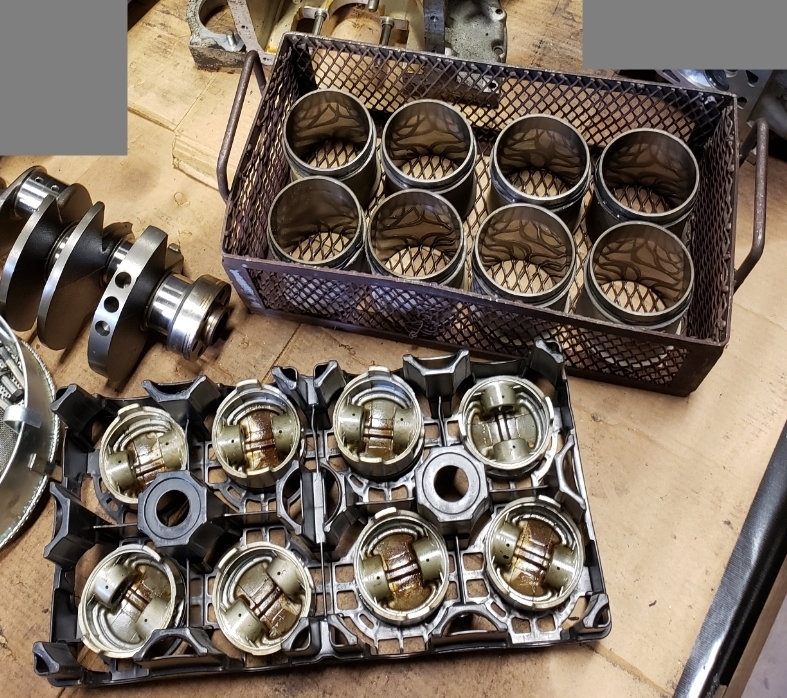
The cylinder liners are in very good condition, with no ridge at all, and only the very top of the bores no longer showing hone marks.... but the liners are likely a few ten thousandths different... so the intention at the shop now is to re-hone, and set all bores to within one ten thousandth (.0001"). With that final figure, I'll pass that along to Traum pistons so we can have the pistons made to the bores, instead of the other way around.
oldeskewltoy said:
I can't be sure.... but there are not many hemi owners who can carry both heads at the same time.... 
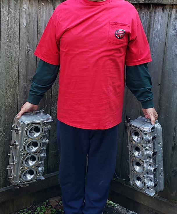
Or their blocks....... 
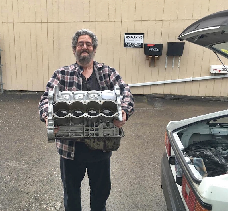
more to come....... 
oldeskewltoy said:
TVR Scott said:
Very cool.
Can you show more of your set up?
What would you like to see???
Whoops, I asked months ago. I'd love to see how you take measurements. Also what you're using for an air source. And fixturing to the head.
Ok, I want to see everything.
TVR Scott (Forum Supporter) said:
Whoops, I asked months ago. I'd love to see how you take measurements. Also what you're using for an air source. And fixturing to the head.
Ok, I want to see everything.

I use a Flow Performance FP2 that I built into a cart. It uses a single 5hp vacuum.

I have bore adapters from 82 up to 86mm.

As to what I'm using for a fixture I have a 1/2" thick piece of plastic that I drill into using a head gasket as a guide, I then lay a .070" thick rubber "head gasket" down, and then using 2 extra large clamps - mount the head tightly to the bench

Each time I use the bench I check calibration using an included calibration plate.

Once calibrated the computer takes the measurement ever 1-2 seconds, I usually run a test for 15 seconds giving me 10-12 samples that I then add up, and divide by the number of readings to get my flow for that port @ that lift.


