So I Failed to do any work last night. But I did do some sketching. Like by hand not on the computer.
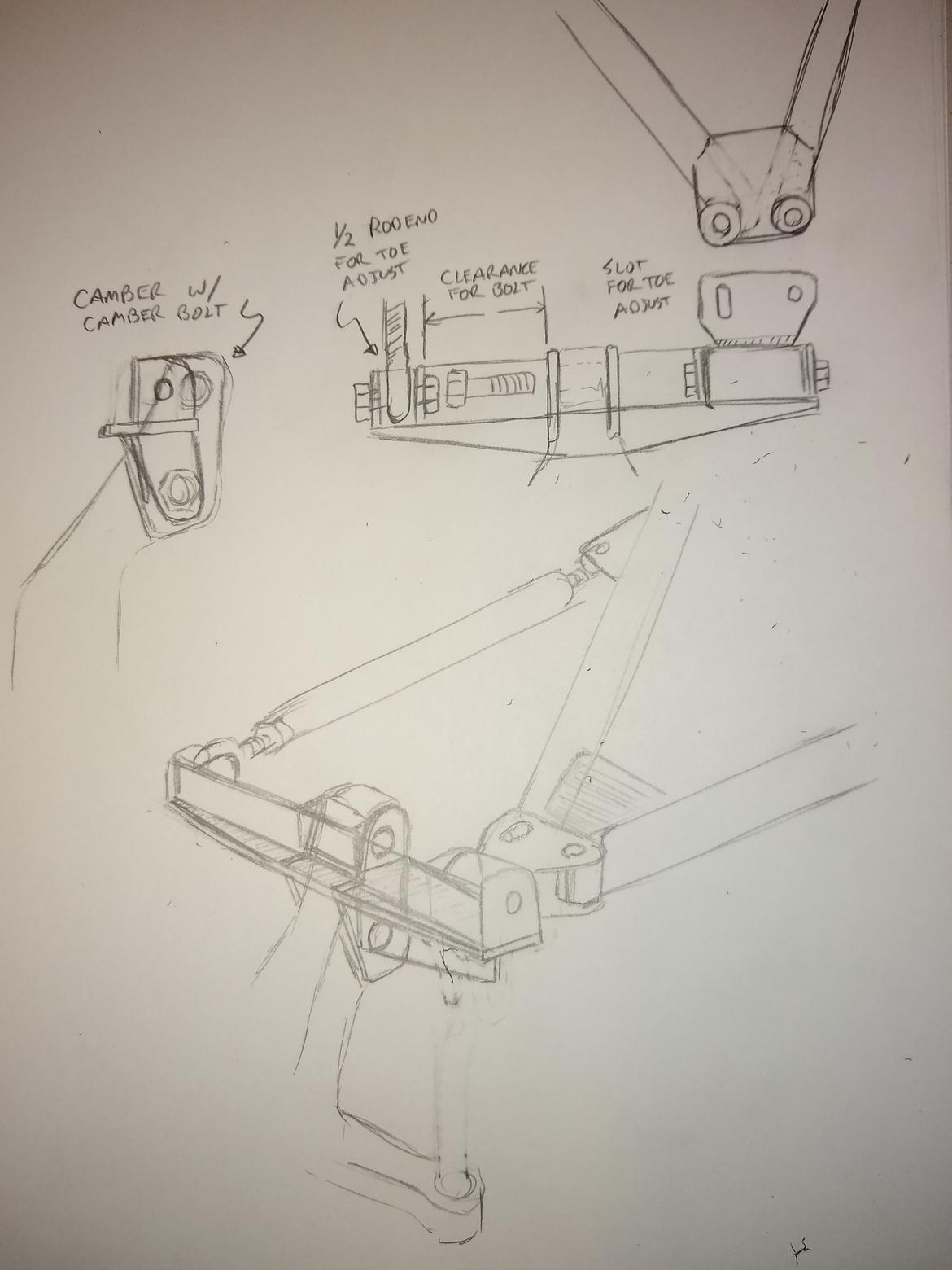
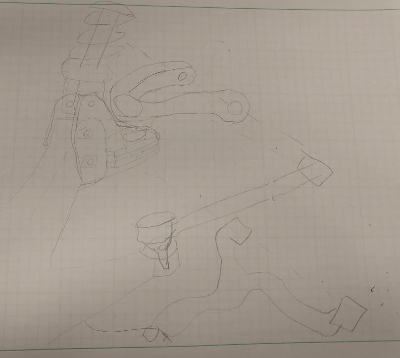
Here is the concept for the rear upright adapter. I may pickup on the stock steering arm or the Brake caliper mount for some additional rotational stability. That said using the stock bolts for camber adjustment makes additional pickups a little more complicated but I am sure I can figure something out.
I'm also undecided on if the Pullrod will attach to the A-Arm or direct to the upright. If it goes on the upright I will need to make very minor adjustments to the Pullrod following camber/toe changes. Those will probably be really infrequent so I'm not sure if matters. Mounting direct to the upright puts a little less force on the A-Arm.
I got the lower rear A-arms front tubes tacked together. They are 22.5" ($5.03 for the pair) and nearly identical. I put a 5* bend in them to allow clearance to the subframe diagonal.
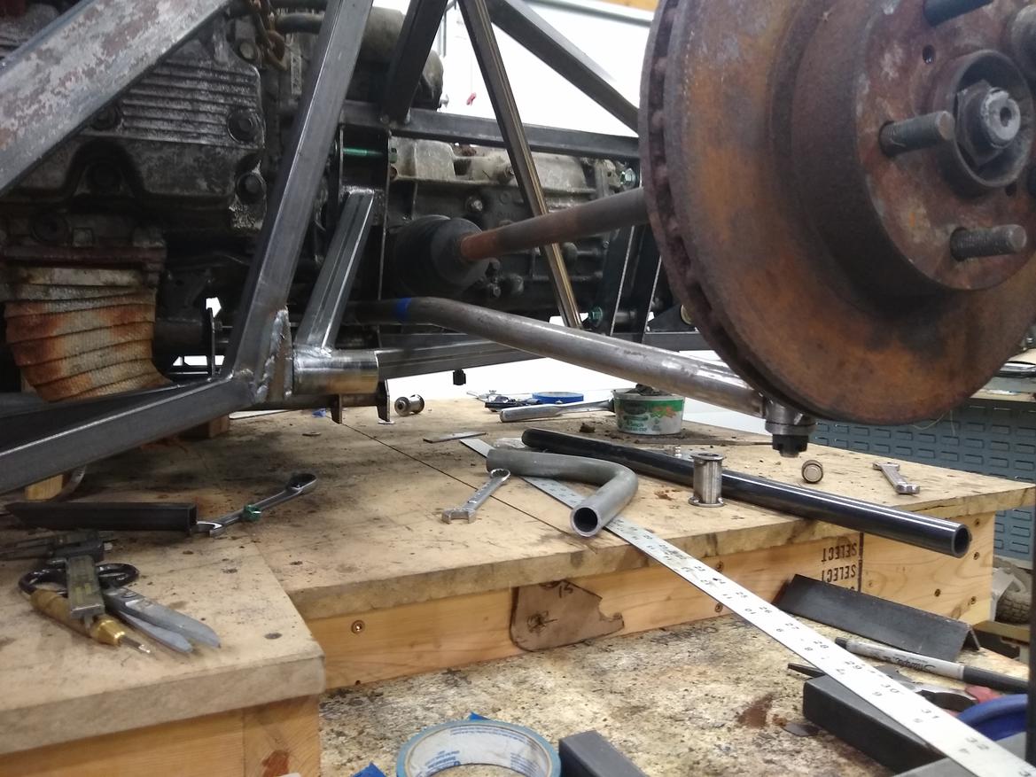
I did let the ball joint shaft angle just be what it is since it isn't that important. They are slightly different but look the same and since they are on opposite sides of the car...
This seems like a big milestone. An upright is sort of permanently attached to the chassis.
+2.25 Hr (167.5)
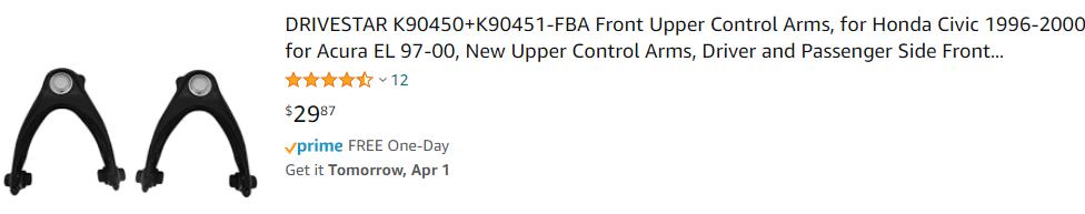
Super interesting stuff, converting a McP upright to double wishbone. I am mulling over the same problem for the Free Range Lotus. My current thoughts involve keeping the steering tie-rods for toe adjustment, delete the rack, and replace rack tie-rod ends with bushed ends to the chassis. But that essentially makes it a multi-link, which is hard to design without berkeleying it up. For UCA, somehow adapting a cheap UCA with integrated ball joint (think late 90's Honda) to the strut holes on the knuckle. I'm envisioning a machined alum or welded steel bracket that accepts the ball joint and one end of pushrod or cheap coilovers. But your control arms are wayyy longer than I have room for, so full custom makes a lot of sense for your build. Since I am nowhere near that step or even that project, I am building vicariously through you.
In reply to maschinenbau (I live here) :
I've thought about running a link from the stock steering arm to the rear shear plates. It would make the upper strut adapter much much easier. Also I could really put the time in to minimize rear bumpsteer to almost nothing. But the consequences are the challenges of a "multilink" rear as you have pointed out, and that I would then have to run an upper ball joint (some amount of $) vs the sleeve bushings (essentially free).
But it would be much less time at the band saw.. I'm going to have to do a think on this one.
Yeah, ideally I would avoid the multi-link, but then I can do something like this, using some cheap UCA's and probably sport-bike coilovers. Requires ball joint reaming though. Holes to the knuckle or holes for the UCA bushings can be slotted for all the adjuztmint.
For after challenge purposes I'd be a little worried about controlling toe through the top mount that way. Seems like not what that part was designed for and with a lot of oscillating forces through that part of the knuckle you might see early failure.
It'd be really low on my list of worries for the challenge however.
I've got a pair of miata 1.6 rear hubs that I'd let go CHEAP, if that's helpful.
Wait, what about running your current plan, but run a solid diagonal bar from the tie rod end mount to the bottom upper hub bolt? This would basically just solidify the hub and minimize the twisting movement in the upper hub arm that you wouldn't want.

nocones
UberDork
3/31/21 10:23 a.m.
I had a similar thought to use the steering arm as reinforcement. The camber adjustment method I was planning to use complicates that, but I could always slot my toe adjuster on the A-Arm mount and do camber there (That's how the rear camber on the MG is adjusted). It wouldn't be independent of toe any longer but it would make picking up off of the steering arm or brake caliper boss much easier for stiffening purposes as they would not need to move relative to the upright.
For the MG I am using the ABS sensor hole on the Miata upright for rotational stability for my steering arm.
Perhaps running a multilink may be an Acceptable. With only ~2.5" of total travel I can probably get the bumpsteer dialled into basically nothing. It would be easy to pickup on the chassis side at whatever height makes sense and just use spacers under the rod end at the steering link to fine tune toe control. The power sports ball joints I'm running in the front are $9 each. So using them in the rear also is a budget hit of $18.
Looking at the A-Arm again I may move the toe link to under the steering arm. To get down to level with the lower ball joint it is only about 2" vertical. I could then run the to link to the bottom A-Arm and have a very simple top adapter. I need to look at what it would take to get the LBJ to Toe link parallel with the Centerline of the car to see if that option would work. It could be the cleanest easiest option. I could maintain camber independent of toe that way as well.
In reply to nocones :
You have so much design flexibility in your chassis and suspension that I'm sure you could nail down bump-steer to near-zero. You're not going to feel 1/8" of toe change from max droop to max compression. You could easily measure it after tacking everything together too.
Plus I want to see you do it first so I can learn from your mistakes 

Rigante
New Reader
3/31/21 11:15 a.m.
i like the idea of for the wide bolt on in place of the strut. As this part could be almost any shape, does making this part taller help with any of the geometry?
nocones
UberDork
3/31/21 11:58 a.m.
I drew up a concept using the steering arm going down. I like the cleaner upper design this allows. The steering link bracket will be a bit complicated because I want something other then friction to ensure the toe link wouldn't rotate. But the force on this would be silly low so I'm probably just overdesigning it.
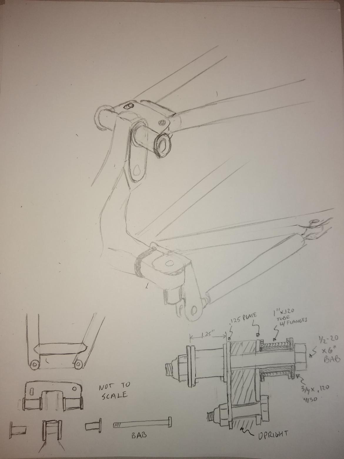
The fabrication simplicity of running it as a optimized multilink may be winning. Assuming I can sneak the toe link by where the shocks are supposed to live..
In reply to nocones :
Wouldn't this one bind unless the upper is also a ball joint?
Just throwing this out here...the Sylva J15 uses an upside down Mac strut hub, do you think you could do the same: J15 Pics
nocones
UberDork
3/31/21 12:37 p.m.
In reply to maschinenbau (I live here) :
The purpose of the wierd lower steering arm bracket is to get the toe link pivot in line with the LBJ so there would be 0 toe change with suspension travel.
In reply to RoddyMac17 :
I had consider running the uprights inverted early on. At this point the chassis pickups require that they stay as is.
It's too bad that gentleman had to sell his project before finishing. The Sylva J15 is a neat kit. Must be very light. I do not anticipate I would actually have any issues if I ran with just the strut mount bolts being used for toe control. The section of the cast upright is huge at that location, but if I can figure out a clean way to load the upright as it is designed I will be happier.
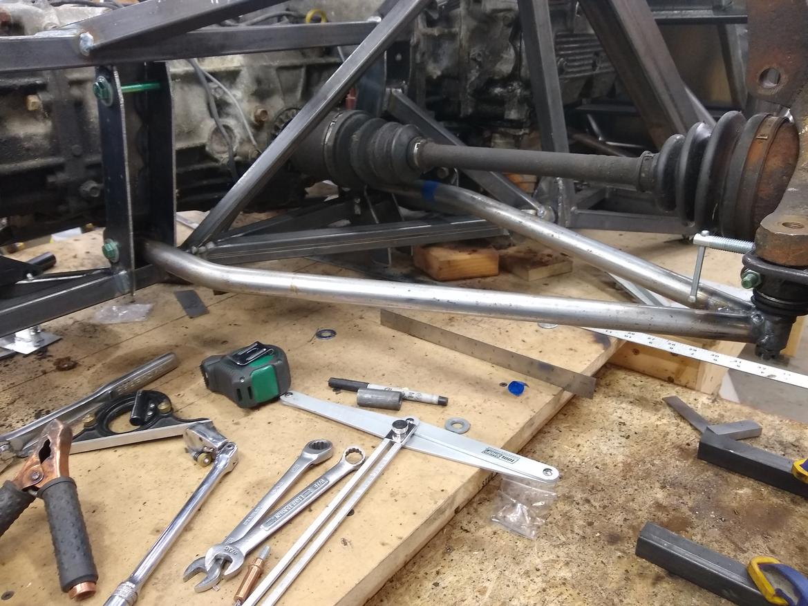
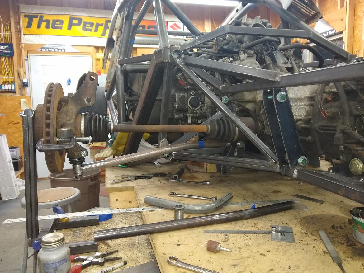
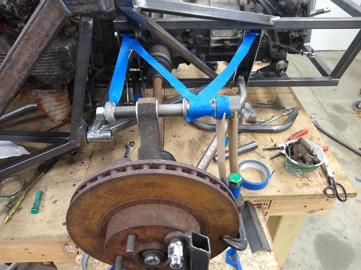
Rear lower A-arms are Done. Fully welded and everything. I may add a bit of reinforcement around the ball joint bung at the tip. I decided to bend the end to make the bushing attachment perpendicular. I realize it's sightly weaker, and if the Tubes where thinner wall or more marginally sized I would be concerned, but they are 1" OD x .120 wall DOM which is a common a-arm tube size on cars weighing 2x what this car will weigh.
I also mocked up the a-arm adapter. I kinda circled back and arrived at sort of the original idea. But I brought in things from all the other ideas people have discussed. I'm not sure how I feel about everything relying on 1 bolt. It's not an uncomon situation though. The MG uses a large 1/2" bolt on the bottom of the upright, the Miata uses it in production. Ultimately basically every production vehicle has 1 bolt holding the upright to the car. For now I would use a Grade 2 coarse thread bolt because <$1 cheap, then I will upgrade it to a grade 5 or 8 bolt after the challenge (But like actually upgrade it unlike the MG that is still running a Grade 2 coars thread 8" bolt on it's rear suspension 100's of track miles later).
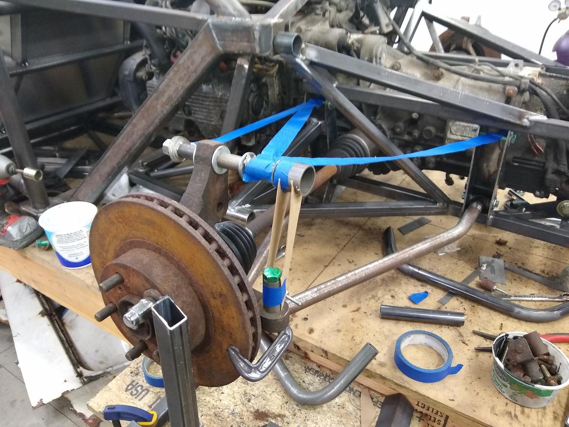
I probably don't actually need the Steering arm support but it makes me feel better. The washers at the upright will be a plate and will use the lower bolt holes also. I will probably end up with some amount of camber adjustment at the upright (The hole is 14.5mm and the bolt is 1/2" so it has some adjustment) and I will slot the a-arm bushing adapter to allow for a little more at the A-arm. My target is to be able to run 0-3* so I can put the tires upright for the Drags.
For what its worth, I think the steering arm support is a worth while addition strength/control wise.
That'll definitely work! Looking good. I wouldn't worry about the tube strength. You should see the thin folded pieces of sheetmetal that pass for control arms on an early Lotus. In a parallel ethereal plane, Colin Chapman is browsing this forum and expressing his disdain for your "overbuilt" tubular chassis, but from behind him his drivers are winking at you and giving a hearty thumbs up.
Cones are trembling in anticipation!

mke
Dork
4/1/21 7:56 p.m.
I'm not convinced the steering arm addition is as helpful as you might want it to be.
Here's an idea. Make the upper a-arm and actual a-anm with an outboard hemi joint bolted to the top of the strut....a grade 2 is fine but since it will be much shorter you can probably spring for a grade 5. Then tie the steering arm to the lower a-arm and just weld a plate to a bolt for adjustment on challenge day, $1 each. later add a couple hemi joints so you can tie it to the frame and not have any bump steer. It will be stronger, lighter, easier to build I THINK..I might be wrong but it seem more right.
Which link will be adjustable for toe-in adjustment? That position needs to have both right and left threads. The other end of the upper outer needs to have 3 dimensional compliance to accommodate said toe adjustment. I would eliminate the forward spacer tube to shorten the upper outer pivot bolt. Just put the rod end against the upright. Your load base is far larger than necessary, especially with the brace down to the steering arm. Machinenbau is right on target about Chapman
nocones said:
Fiat controlled rear toe in a very similar manner on the X1/9 (strut, obvs.). In working through a similar problem, I figured that the toe link didn't have to be inline with the lower A-arm, as long as the two are linked, the upright will move in the same arc. Am I wrong? (legitimate question, I know butkus, but am trying to learn.)
For what it's worth, I had imagined putting a riser on the lower arm to get closer to a straight line. Note: I'm sure you have this all well in hand, I just like yammering on the interwebs sometimes.
In reply to wheelsmithy (Joe-with-an-L) (Forum Supporter) :
Unfortunately you are wrong. The toe link needs to be parallel to the control arm in the horizontal plane, as it is in the Fiat. putting it off parallel introduces roll steer/bump steer. Often done deliberately by the OEMs on street cars.
In reply to mke :
The biggest issue with that idea is Heims really should only be used as 2 force members. Meaning they shouln't be used to take significant radial or axial loads that are not along the axis of the threaded shaft. I know it's popular to miss use them (And I am using a 3/4" one on the MG front upright) but I'd like to avoid it in this application. Or I would be compelled to run a 3/4 or 1" joint (which are expensive) so I can be sure the ~10% axial load limit is maintained. The upper arm has to take the spring loads because I don't trust the OEM Subaru ball joint to take those loads. This puts increased demands and loads on the upper ball joint. That's why I'm planning to run the metal sleeve bushing which will be able to handle the load but can only rotate in 1 direction.
I am also not sure how much support the steering arm will provide. The design would allow this to be removed if it doesn't seem necessary to save weight and money.
I'm appreciative for the thoughts. This is one of those 10 different ways to do it none of them are perfect things so the discussion even of concepts that don't end up getting used is helpful.
In reply to TurnerX19 :
He is for sure right about Chapman but I don't have the luxury of replacement drivers if I cause a crash and damage the one I have.
The toe base looks large but it's about the same as the length of the OEM steering link. The spacers are just random lengths I had. I will likely shorten the one for the heim by about half. The heim joint is the one that will control Toe. The sleeve behind the upright will be the upper bushing and will require a bolt on adapter for the A-Arm to accommodate toe adjustments.
I have thought about just bolting the heim to one side of the upright and the bushing to the other and have about a 3.5" toe base. That basically would require me to trust that the upright could handle toe control through just the torsional rigidity of the strut clamp. It's probably fine.
But if moving the bushing away from the upright and adding the steering link takes even just 25% of the torsional load off the strut section it's worth it.
In reply to TurnerX19 :
I appreciate the input, and hope to not thread-jack too badly, but if you can offer it, I'd appreciate clarification.
In the X's case, the tie rod simply locks toe to the control arm, unlike say an AW11 MR2, which has toe change throughout its travel. If toe changes, it is related to the shape of the lower control arm, specifically the fact that the two inner pivots are not in line, right? NoCone's car has those inner pivots inline, so the toe change would be caused by the castor-meaning the top ball joint moves fore and aft in relation to the lower. Am I getting anywhere close?
This is not meant as an argument, and I promise to let OP get back to it soon.


