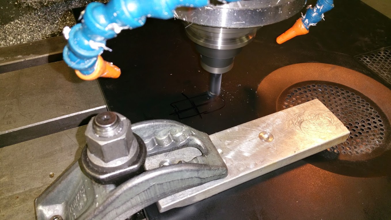
Most of you probably know my dad and me from our other thread about building the DF Goblin (if you don't want to read the thread you can get a quick rundown at our site DF Kit Car) and you've all probably noticed that we've been a little quiet. Well we haven't had much to post about the car because we've been busy building a CNC bender for about a month and a half.
So why did we decide to build a bender rather than buy one? (I can't believe anybody on the GRM Builds and Project Cars forum would ask such a question, but I'll answer anyway)
The CNC benders we browsed through cost too much and were overqualified for what we needed to do. When we were building the first Goblin, we made things easier for us to manually bend by designing each piece to be bent in a single plane. We are sticking to single plane bends in the production frame, so we don't need a full 3D bender.
Here's the requirements we designed the CNC bender to meet:
- low cost
- able to bend 1.5 inch and 1.25 inch tubing
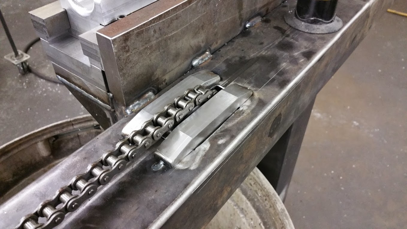
- chain driven feed system capable of moving the tubing >200 IPM
- easy to load
- hands off operation after loading the tube
With these requirements in mind, we bought a few hydraulic cylinders from Northern Tool and some DIY CNC supplies from Probotix (I highly recommend Probotix for CNC projects, they were incredibly helpful). Then we got on Solidworks and drew a bender around these parts. Here's a mostly complete model:
A basic rundown of whats in the image, starting from the left:
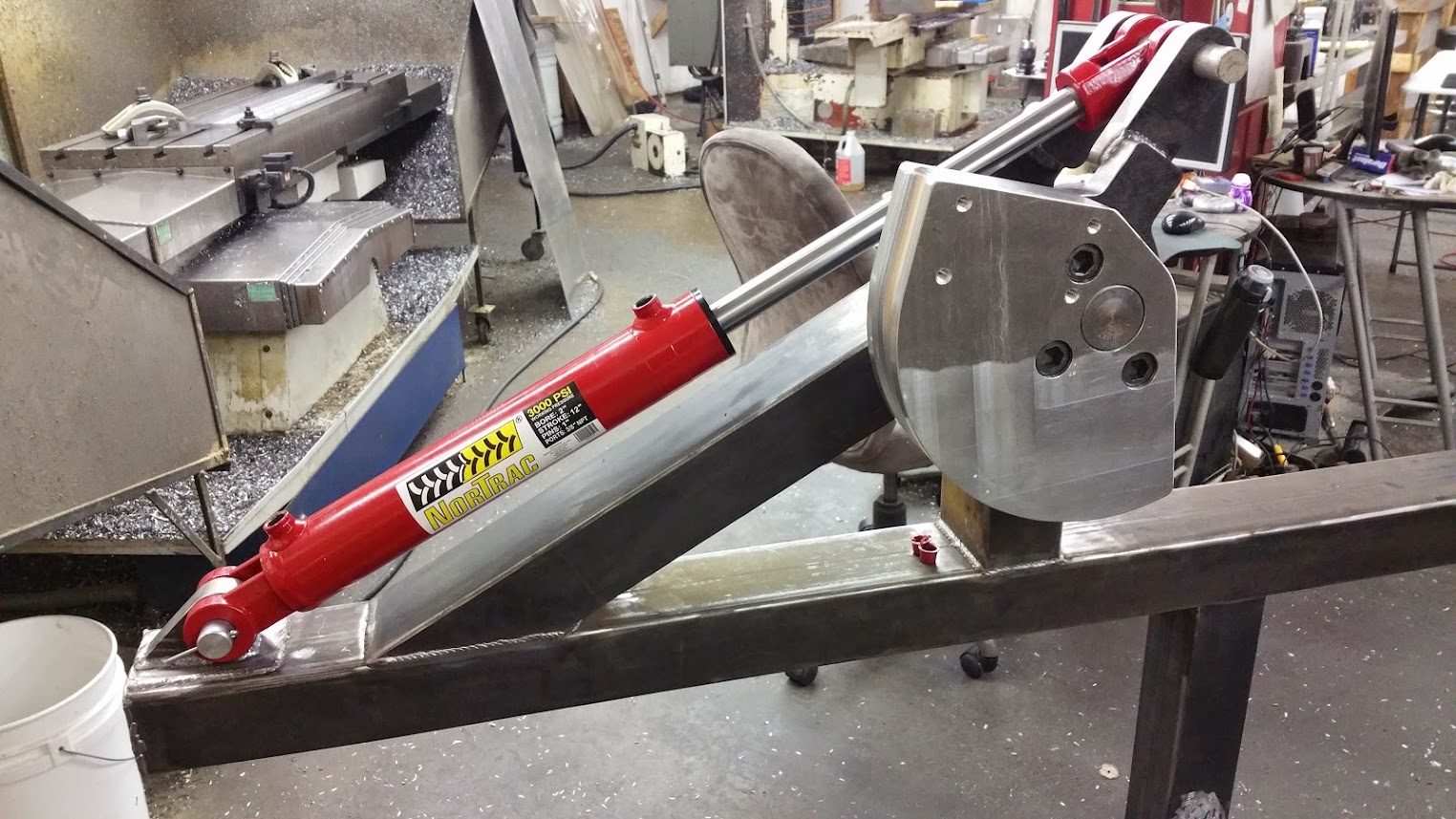
We have a single bending ram that rotates the bend dies (we have two dies because we went with a "double barrel" design that has dies on one side for 1.5 inch tubing and dies on the other side for 1.25 inch tubing. This way we don't have to change out anything to switch between tubing sizes).
Attached to the bend dies are clamping rams that hold the tubes to the bend dies. Also attached to the bending dies is a homemade optical encoder that measures the bend angle to 1/4 of a degree (you can't see the encoder in the model).
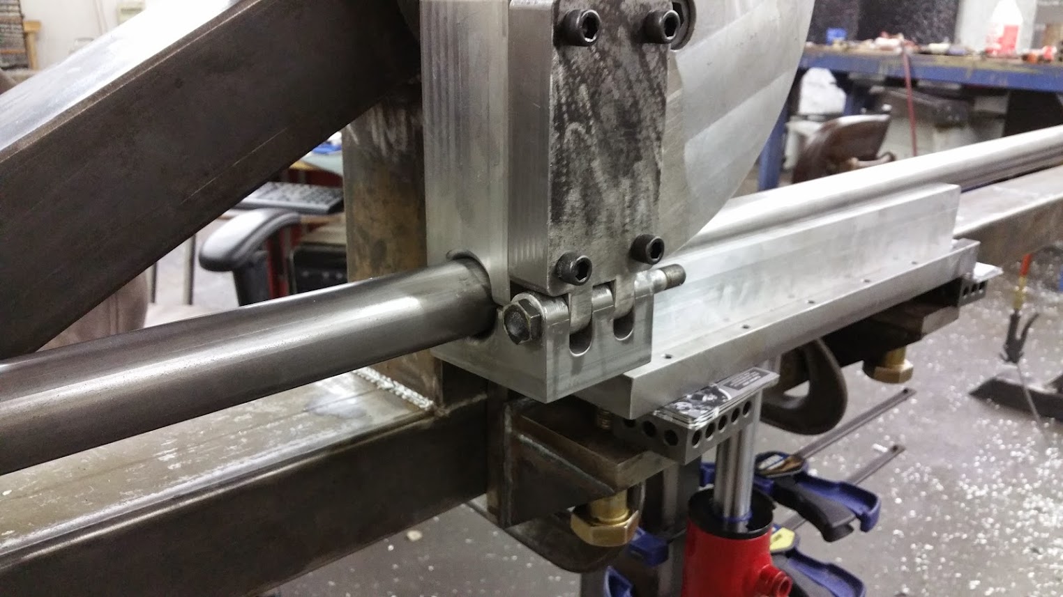
Above the yellow pieces are the pressure dies. These slide forward and back as the bender bends to keep the tube against the bend die.
Holding up the tube in the image is what we call the tractor. It has a one way clutch that locks when the tractor feeds the tube but freewheels when the bender pulls the tube. Allowing it to freewheel means that the tractor and bend ram do not have to be synchronized during bending. Not shown in the image is the chain that drives the tractor.
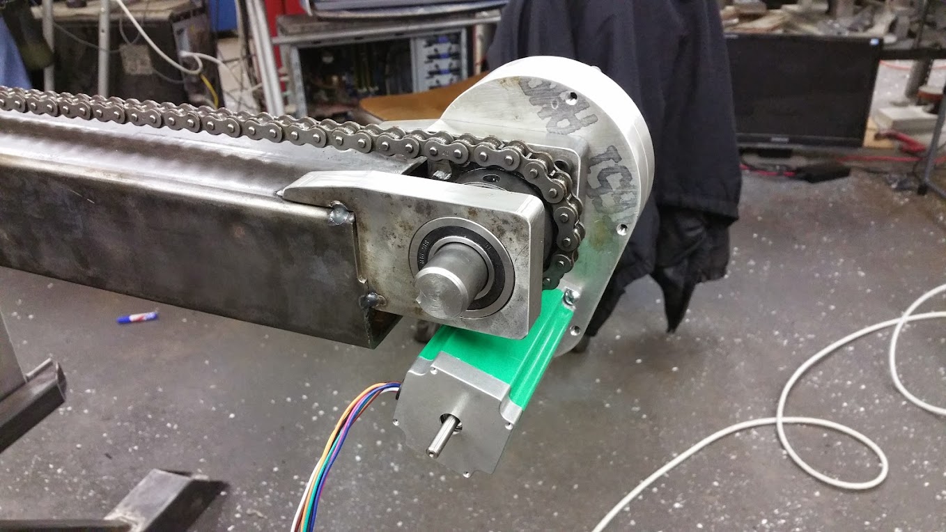
All the way to the right you can see the stepper motor and gearbox that drive the tractor chain. You can also see tubes sticking out to mount the hydraulic tank. The motor and pump will be mounted opposite the tank, on the near side of the model.
Most benders like ours bend the tubes flat to the ground, but we decided to bend ours up toward the ceiling to conserve space. Our largest pieces will extend less than five feet above the bender and will weigh less than 15 pounds so unloading won't be an issue.
In my next post I will get into the actual build. I just wanted to give a summary of the project first.


